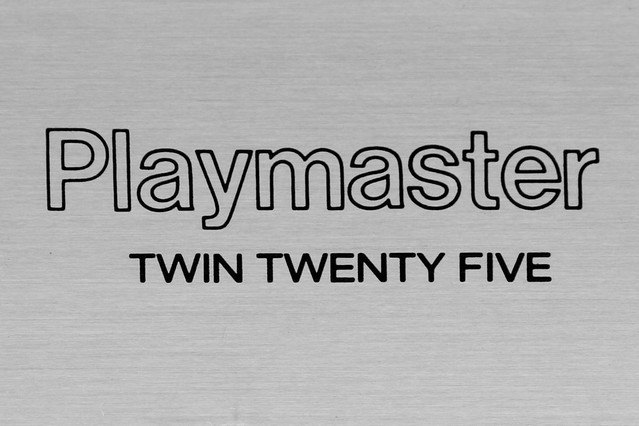
You may not instantly recognise the brand Playmaster immediately, especially if you're not from Australia. To be honest I didn't either, but the name rung a bell. Down under, we once had a magazine called "Electronics Australia" they would periodically release designs and sell them in kit form under the name Playmaster. Ranging in valve and solid state equipment, a lot of their earlier work was with Guitar Amps and PA amps, however they did do HiFi as well.
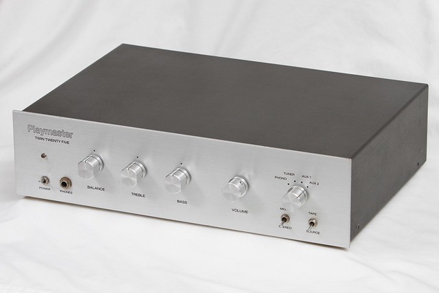
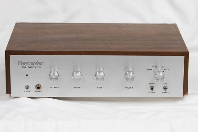
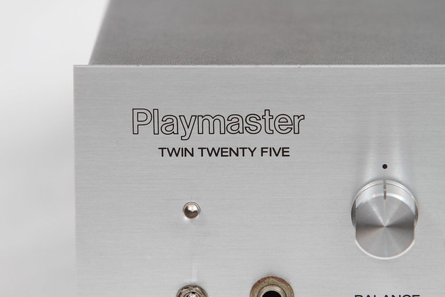
Quite beautifully built, brush aluminum faceplate, Solid machined aluminum knobs, and a nice simple design that's not cluttered. It's exactly what a nice simple amplifier should be. Simple!

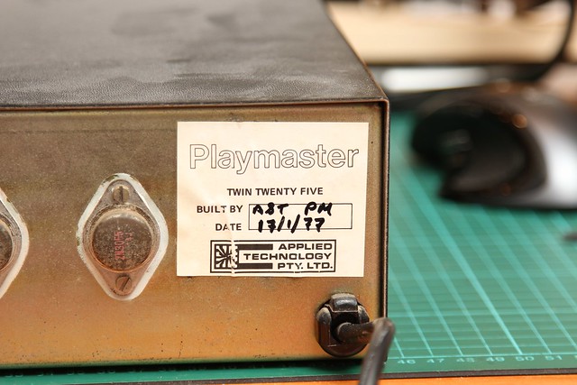
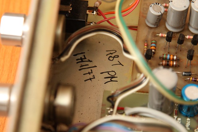
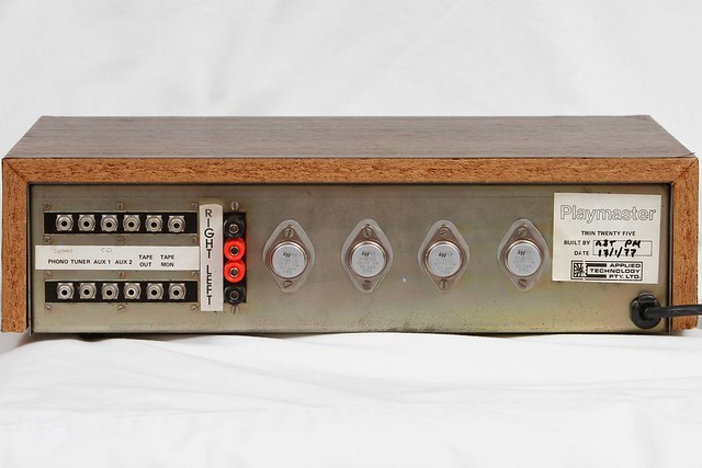
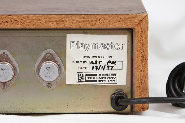
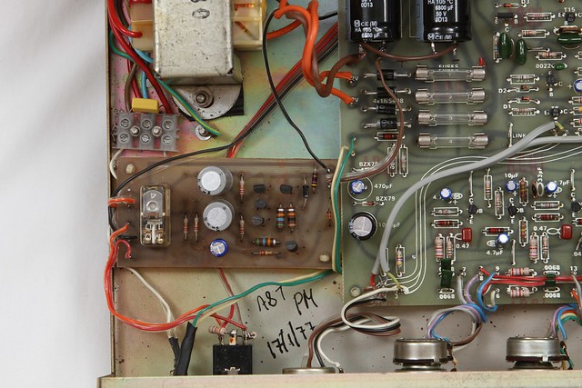
Because these were usually available as a kit form, as Electronics Australia was predominantly aimed towards the hobby and enthusiast audience it makes this little amp even more special as it was a factory built by Applied Technology Pty Ltd. It even has the date of manufacture and the sign off by the technician(s) who built the unit. In this case the build date being 17th of January 1977, pushing this little beauty just past it's 35th birthday. Although by the time it's restoration is done it won't look a day over 1 :)
This particular amplifier was found, piled up with a bunch of other classics I also acquired and will (eventually) post on this blog at a local charity store. I bought it and only afterwards realised there was a sticker on it saying "not working as is". The wood sleeve was broken, veneer lifting, and was just not in a happy place.
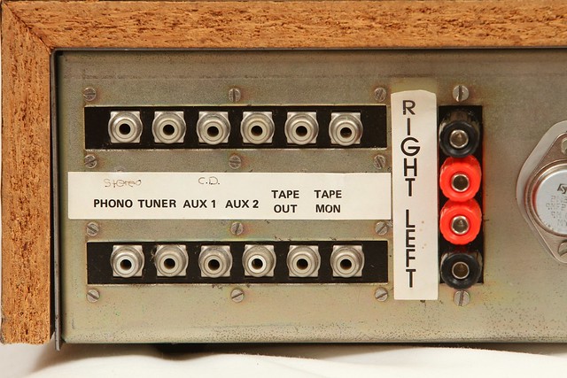
Just looking from behind, I suspect that the speaker terminal connectors once had plastic sleeves, or at least one could hope that they did. Chances are this suffered a slow and painful death from too many speaker shorts.

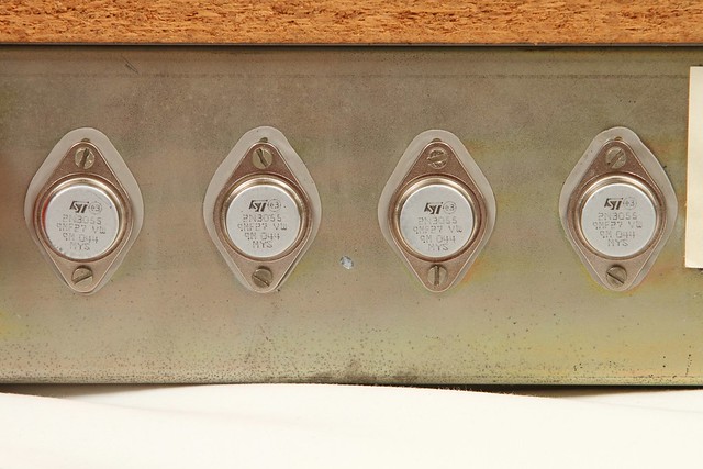
It's output transistors looked the worst off, with a nice layer of corrosion on them. Overall externally the unit didn't actually look too bad. Bit of dust and 35 years of grime :)
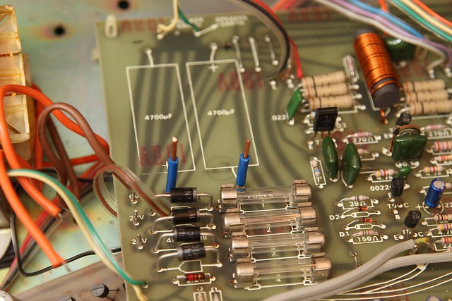
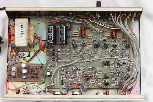
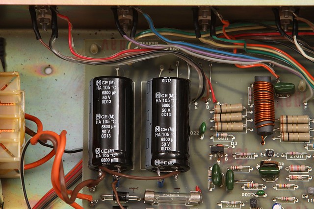
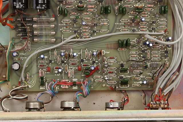
Internally was quite a surprise however. Because it's main output transistors were externally placed there was no need for ventilation inside. As such, like a sarcophagus (ok, maybe a bit of a stretch) it was in excellent condition.

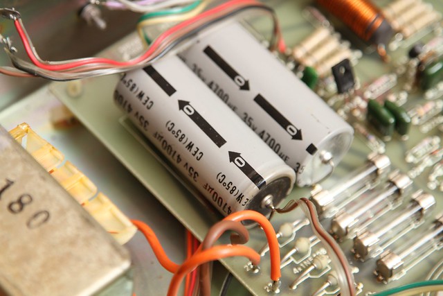
However it did not come without it's drawbacks. Unlike most of the equipment I restore, there was no underside access, so the whole board would need to be lifted in order to replace parts. A speaker protection circuit was added (bottom left corner) presumably by the manufacturer, a nice addition even if it's tapping it's power straight off the main filter capacitors. Speaking of, the main filters in this unit were 4700uf 35uF ELNA caps, respectable for it's time.
There were a few other caveats about this unit that didn't sit well, such as exposed or badly soldered joints, but nothing that could not be rectified.
Initial tests of the transistors prior to firing up showed that both output pairs were toast. As well as a couple of switching transistors. The diodes that made up the bridge rectifier were leaking current, two fuses were blown, several leaking capacitors, including the main filter caps where one was reading 900uF and the other was reading about 5500uF. There was no point in even attempting to fire this unit up, I'd probably be causing more damage.
With all that in mind, let's get started on the restoration!
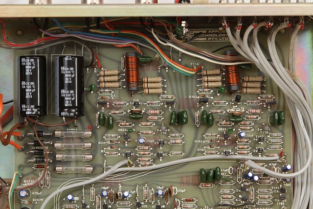
As one customer of mine pointed out recently, I like to treat all of my restorations like restoring classic cars, reducing the amount of modifications, only were necessary or where a substantial improvement true to the original idea can be made. With that in mind, although having the clearance I did not want to drill a couple of additional holes in the pcb to allow the vertical placement of the main filter capacitors. Opting to use a strong but relatively easily removable adhesive to keep them placed horizontally. My star performers as always, a pair of Panasonic TS-HA capacitors, rated at 6800uF. I used 1.5mm thick solid core copper to create two 'imitation posts' where I could connect the caps.
After which the capacitors were bonded onto the PCB..

The rest of the capacitor replacement went smoothy. Tantalum capacitors were replaced with electrolytic or film where applicable. Panasonic AM series caps used for all electrolytics. To get to the bottom of the PCB, all the potentiometers had to removed from the faceplate, everything was hard wired in! But never an issue for me :)

Next up was the speaker terminals.. Pictures can say a thousand words, though maybe not so many are required to describe this...
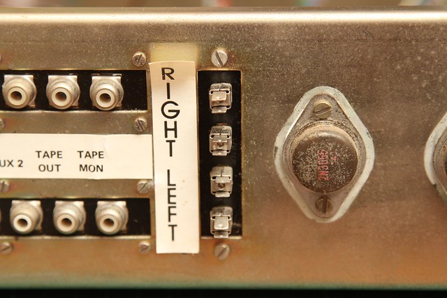

Enough said.
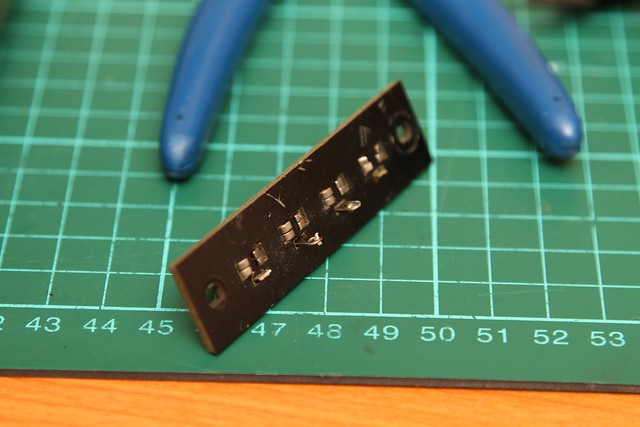
With the speaker connector plate removed, I didn't want to fashion some kind of plastic plate job on there, at the same time, my large binding posts I had for this project were to large to fit in place. I settled on some smaller binding posts. Using the existing plate, I drilled out the holes for the binding posts and fitted them.
Before:
After:

When installing them back on, I did solder the -ve/ground posts in place, however the +ve posts were screwed on.


A much better and safer look!
Alright next up transistors. The switching transistors were replaced on the PCB itself, but the output transistors were connected to the frame for heat dissipation. Given that they had all failed, replacements were ordered in, same type (2N3055) made by SK.
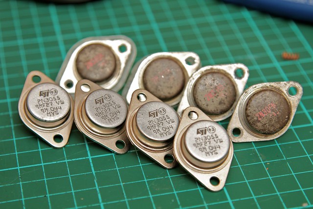
I actually bought a few too many, for starters it's nice to have spares, but secondly so I could hFe match them :)
Before:

Half way through replacement, still removing the old mica film and thermal grease:
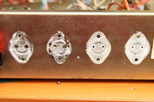
After:

New outputs, cleaned all the old gunk off, new thermal pads, perfect!
A couple of other small things had to be sorted out, a lot of time was spent putting heatshrink tube over exposed wires reducing the risk of anything going wrong in the future. A prime example is the power status led.

Nice and clean now..

After cleaning all the pots and switches, testing the speaker protection relay and some more cleaning it was all done.
The result? A very good sounding unit! Nice and clean, there's not that much 'warmth' to it as you would find in other brand name amps, I find it akin to the Harman/Kardon sound. But it's very clear. I opted to leave the original OP Amps in place (LN741) as they were giving no troubles and would retain it's original sound.
Overall, I like it! With a touch of tweaking to the bass and treble I could easily find a place for this little beauty in my home! However, like I've said before, the way an amp sounds is quite subjective to the user, I could rave on for hours describing the "sound" but it's my interpretation of it. Yours would be different, in fact I would be shocked if it was not!
So that's the Playmaster Twin Twenty Five. A beautiful simple 25wpc amp. As always some modeling shots below, please feel free to comment and shoot off any questions if you have any. I hope you have enjoyed reading this article, I certainly enjoyed working on it!


My phono input does not work however, all the other inputs are fine. I have misplaced my schematic drawing and it has worked faultlessly since I assmbled it from a kit in the mid 70's. Does anyone out there have a copy of the schematic they could scan and post?
ReplyDeleteAll is well as I have now found the assembly manual. The completion date of the kit was 22/12/1978 and has worked ok since. Now, to fix the problem of no output of the phono into the preamp. If anyone needs a copy of the manual, please email me at blues7591@gmail.com
ReplyDeleteGood to see another Twin TwentyFive owner out there! If you have not already, give the unit a re capping, especially around the phono stage. If you're lucky it's only a dried out capacitor. Otherwise the good news is that all transistor components are still available through most online outlets so getting it sorted out won't be an issue. Have you given the input switch selector a good clean with electronic component cleaner yet?
ReplyDeleteThanks for putting this information up. I built a Playmaster Twin 25 in 1976 and it has continued to work faultlessly until just recently. Now when I turn it on there is a rumble emanating from both speakers which sound like waves breaking on a beach. The noise and loudness does not alter with changes to volume, bass/treble but it does disappear if I turn the balance hard left.
ReplyDeleteGood news. I just turned the unit on a minute ago and I continued to turn the balance hard left to hard right and back again several times, and (maybe luckily) the rumble seems to have disappeared, at least temporarily.
Could this simply be a problem of dust in the balance potentiometer?
I have replaced the balance potentiometer but unfortunately the rumble persists. erhaps the problem is on the board
DeleteThe Playmaster Twin 25 was my second home made amplifier, the first was the Playmaster Twin 10.
ReplyDeleteBoth great performers. This article brings back good memories.
Also at the same time I built bass reflex speakers in kit form. The amps are long gone, though the speakers are still working OK in 2013!
I have used the Twin 25 for quite some years now, coupled with the Playmaster 3-45 speakers with upgraded bass and midrange drivers, which sound very sweet. I still use it in my lounge room and it is more than adequate in that situation. Good to see your blog and the restoration of the amp.
ReplyDeleteI started off with the Playmaster Twin 10 valve amp and also built the Playmaster 138 amp, which was also very good, except for the power supply that had a sensing circuit for shorts, and that was not the best, so I went back to a simple power supply and fused the amps.
I have used the Twin 25 for years and find it more than adequate in my lounge room. I use it to drive the Playmaster 3-45 speakers with upgraded bass and midrange drivers, and they sound very sweet.
ReplyDeleteGreat to see a really good description of the restoration. Well done!
I have also built the valve Playmaster Twin 10, and also the Playmaster 138, which was a great amp. Still have them in my workshop. Maybe one day a restoration project.
I found on taking the lid off that mine is the Twin Forty version with the upgraded power transformer etc. So that is an interesting discovery. In the years since, I forgot that it was the bigger amp., not the Twin Twenty Five. I think it is still a nice amp.
ReplyDeleteIn 1976 I was in my final year of a radio technicians course with the RAAF. I chose the Paymaster 40/40 as my practical assignment. It's still going strong. This was a top design by Electronics Australia. Extracts (schematics etc) are available from Silicon Chip Magazine.
ReplyDeleteI gave my twin 25 to my son who has had years of good service from it. Recently the power switch went down to earth and took out his flat's circuit breaker. I replaced the power switch with one of a higher spec, inserted a vero board containing a 6 volt xformer, rectifier, smoothing cap, MOC3041 driving a triac to switch the power to the amp. The power switch only supplies the 6v xformer primary. I also added a 3AG fuse holder and fuse.
ReplyDeleteThis article is very valuable to me as it gives me a host of other things to look for. This amp of my son's must be at least 25 years old.
Many thanks
Kevington Beare
The Twin 25 was my first serious project, and it performed well for quite a few years. I then lusted after more power, and built the Twin 40, which also performed really well for years. I then got hold of a demo Denon 80W per channel stereo tuner amp.
ReplyDeleteUnfortunately the Playmaster amps were then cannibalised for parts for ongoing projects.
When I built the Twin 25, I also purchased a pair of Playmaster designed speakers, in kit form with Magnavox speakers. Amazingly, these still work fine, the original cones remain in good condition. The Denon and the Playmaster speakers have been taken over by my 25yo son.
Nice work I just picked one up from an opp shop for 5 bucks I'd like you to do your magic on the internls
ReplyDeleteNice work I just picked one up from an opp shop for 5 bucks I'd like you to do your magic on the internls
ReplyDeleteAmazing restoration of a very beautiful amplifier, I have the Playmaster 136 which is still in it's original condition since someone built it and still going strong powering a pair of Realistic 15" three ways. 13W RMS per channel from it's (now very rare) TO-66 transistors produces amazing sound quality with the speaker combination that I have it in... I would say that mine is way overdue for a refresh even though it still functions and I'm going to take plenty photos of before and after just as you did. Also while the PCB is out, I will reverse engineer the PCB and then make a CAD drawing of the schematics for it just in case new PCB'S are needed in the future.. I have a feeling that this one is going to stay in the same family for a long time.
ReplyDeleteThe first EA I brought had the Playmaster 25 on the cover. Around 1976 I think. I built the 40/40 and used it until I built the Black 100W Playmaster. Also built the AM/FM receiver.
ReplyDeleteThanks for the story
Brilliant article, thanks for taking the time to post it. I built a Playmaster 40/40 as a project when a 1st Yr OTC Trainee in '81. I rewired and cleaned it up over several midnight shifts in the late 80s and used it for years. It eventually failed in one channel and I suspect a MOSFET. You have given me the impetus to dig it out and restore it to working order, maybe a joint project with the grandson. cheers
ReplyDeleteBuilt one of these when I was 15, had to save and work a lot to be able to purchase the kit
ReplyDeleteGreat to see some love for the Playmaster series. I built the twin 50 Mosfet version, and the Playmaster 3 way speakers....which I have kicked myself ever since selling.
ReplyDeleteYou and me both. For what they were, nothing comes close to Playmaster gear
Delete